The microscopical applications of bicolour polarizing filters |
| © Spike Walker 2007 |
|
1. Colour Phase Contrast
Beginning with the (16mm thick) Izismar Chromostar in the early 1970s, a number of manufacturers have produced photographic filters of which the colour may be varied continuously by rotating a polarizer behind (or in front of) them, though usually at the expense of fairly astronomic exposure factors. The Chromostar gave yellow to blue via greenish-yellow intermediates, while the two (?) Pentax Fantasic filters yielded blue to red via pink, and green to red via orange. These three incorporated their own linear polarizing filters but the Vivitar Cromo Blends (1976) were supplied without one. All of these seem to be difficult to find now, but Cokin have recently introduced five under the name Variocolor. They are red-green, blue-red, magenta-orange, blue-yellow and purple-lime green and, like the Cromo Blend, are normally used in combination with a separate polarizer. Hoya also list five called Vario PL-Color, nominally red-green, red-blue, yellow-green, yellow-blue and yellow-red. (not to confused with their ‘Pol Color’ series which merely change from a single colour to neutral).
|
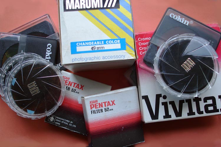
Fig. 1. Bicolour polarizing filters by various manufacturers. |
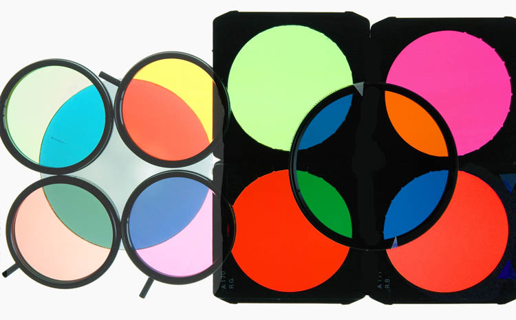
Fig. 2. Two sets of bicolour filters, each shown combined with a linear polarizer. Left: by Marumi, Right: Cokin. |
In contrast to those by Cokin, the Hoya filters look very pale and vary, for instance, from dull terracotta via grey to grey-green (R-G) and from a rather brighter terracotta via khaki to yellow-green (Y-R). Of the Cokin examples, the blue is a 'peacock', the 'purple' is magenta and the 'yellow' is decidedly orange, but the 'red' and 'green' are above reproach. All, with the exception of 'lime' are clean and saturated. Pentax's red in the R-G version has an orange tint while the green is 'jade'. In the B-R example, the 'red' is well toward orange and the 'blue', dull cobalt. The only Cromo Blend seen so far, marked 'CB R/B' is like a less saturated version of that by Cokin. A set of five filters (B > Y, Y > G, Y > R, R > B and G > R) have been marketed under the trade name ‘Marumi’ as ‘changeable colour filters’. Their rotating mounts do not incorporate a linear polarizer and their colours are very pale.
The Cokin examples are in the familiar square plastic mounts, which allow the 60mm circular filters to be rotated, if necessary, by the application of a little force, or (reversibly) removed. It is convenient to turn them so that their planes of polarization lie parallel to the sides of the mount (fig 2). The filters by other manufacturers are in conventional circular aluminium mounts with or without a linear polarizer rotating in front of the bicolour screen (Pentax) or behind (Hoya). Their relative positions are of no consequence when the filters are used in front of a camera lens, but, in their microscopical applications, the filter must always be nearer the condenser.
For photographic accessories of such apparently limited utility, they are surprisingly sophisticated in construction, incorporating, as they do, a filter which is capable of converting un-polarized white light into two beams of different colours, linearly polarized at right angles to each other. They have a sufficiently strong polarizing effect to allow their use in some microscopical applications without the aid of an additional polarizer, with a consequent (fairly vast) increase in light transmission (but see later). According to Ray*, the coloured component comprises "a sandwich of dichroic plastic material which selectively retards the various wavelengths, and this is followed by a colour filter to absorb one waveband, such as green [in a B-R example] (Rothschild 1976*). The ‘analyser’ [the linear polar filter] then transmits different amounts of the remaining red and blue bands, giving a red to blue transition." However, not all the filters seem to be constructed in the same way: in their applications in microscopy the 'Hoya' type, for instance, behave completely differently from those by Cokin.
2. Phase contrast with colour modulation
The phase/fluorescence version (46 52 78) of the Zeiss (Oberkochen) VZ series of condensers has a rotating turret containing 4 phase contrast illuminating annuli, two (Ph2 and Ph3) of the conventional type and two, numbered in blue, in which the annuli are 'etched' into a linear polarizing film. These annuli allow a switch to be made from a fluorescence to a conventional phase contrast image merely by rotating a polarizer below the condenser and by removing the excitation filter. (In fact, Zeiss supplied a 'light moderator' containing two polarizers which can be rotated independently, making it possible not only to enable phase contrast but reduce the intensity of the illumination to a safe level.)
If a bicolour polarizing filter of the 'Cokin' type is placed between the microscope’s polarizer and the condenser annulus, with the correct orientation, a phase contrast image can be produced with additional colour contrast. The specimen then takes on an approximation to the colour of the illuminating annulus, against the background colour of that of the rest of the disc. e.g. orange against a green background in the case of a red-green filter. The contrast can be increased significantly by a slight lowering of the condenser. The colour combinations may be reversed through 90°, but one image, e.g. red on a green ground, is invariably much paler than its counterpart, green on red.
The direction of polarization of the condenser annulus plates is N-S and, for optimum contrast, that of the desired background colour from a given filter (e.g. green from R-G) must lie in the same direction. If, at the same time, the microscope’s polarizer is E-W, the R-G filter will give a monochrome image in shades of red, but, if the polarizer is then slowly rotated in a clockwise direction, the background gradually lightens and becomes increasingly green. The best compromise between overall image brightness and colour contrast occurs at about 40°S of E-W. Since, however, even a slight displacement of either filter or polarizer will produce a disproportionately large change in colour contrast, final adjustment requires nice judgement and a delicate touch.
|
 |
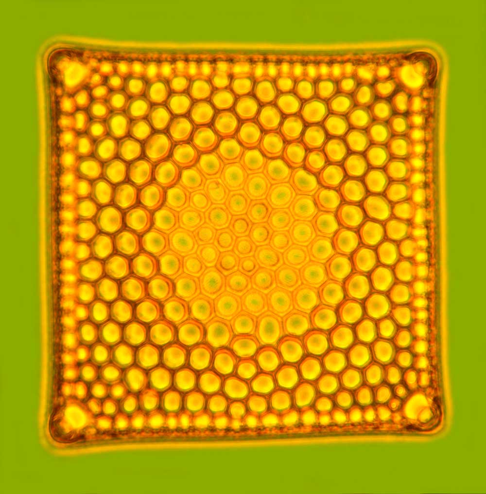 |
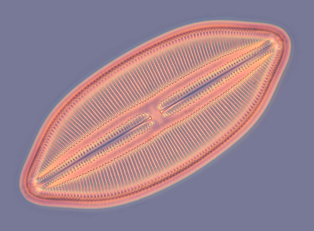
| Fig. 3. Diatoms in resin, colour phase condenser, fluorescence-phase condenser : Left, Navicula lyra, 40/0.75 Ph2 Neofluar; Right: Triceratium sp. 4-angled, 25/0.65 Ph2 planapo. |
The technique is very effective with such subjects as diatoms in resin (fig ), and ‘pondlife’, etc. in water, where the image produced resembles that yielded by Rheinberg Illumination, but with the enormous advantage of working with objectives of high aperture and magnification, even the 63/1.4 and 100/1.3. In these cases, however, the colours are less saturated than with objectives of moderate N.A, though they are easily ‘tweaked’ with photo-editing software. No less important is the fact that the more weakly-retarding parts of a preparation produce a conventional phase contrast image in shades of the 'background' colour.
|
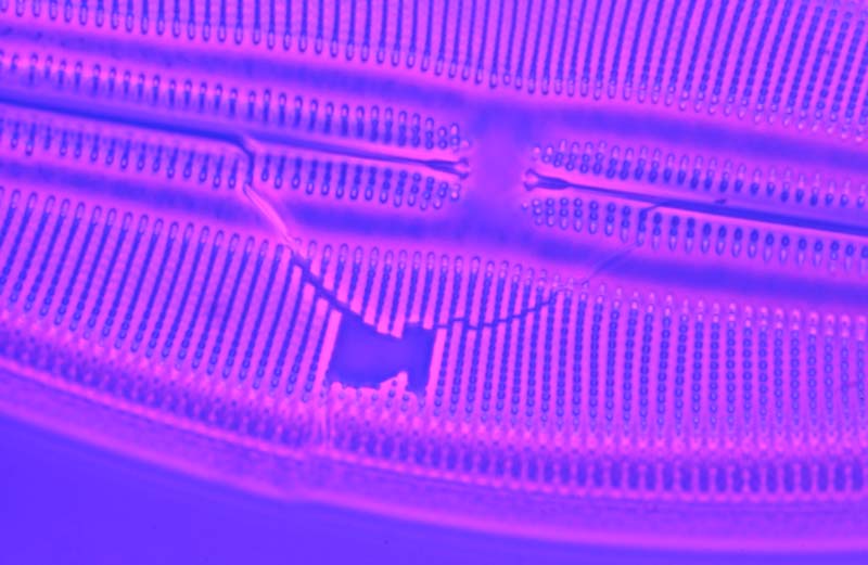
Fig. 4. Navicula lyra, postage stamp fracture, colour phase contrast with fluorescence-phase condenser, 63/1.4 Ph3 planapo. |
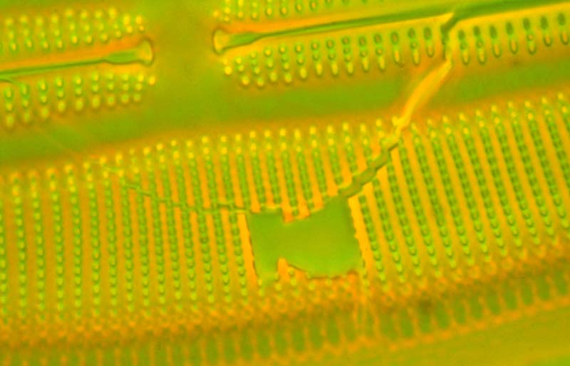
Fig. 5. Ditto, 100/1.3 Ph3 planapo. |
A number of ways of producing ‘colour phase contrast’ were proposed in the late 1940s and early '50s* and, this seems to be another. That phase contrast is an important component of the present technique is indicated by the fact that most of the contrast disappears if the illuminating annulus is de-centred with respect to the objective’s phase plate. The contrasting colours are simply derived from the condenser annulus and its surround. With a conventional annulus in place, the image yielded is a straightforward phase contrast one, its hue depending on the bicolour filter being used and, if a polarizer is present, the latter's orientation. Under these circumstances, and in the absence of the specimen, the BFP of the objective shows the annulus in one of these colours, against a black background. On the other hand, using the fluorescence phase annulus, and with the polarizer and 'filter' properly orientated, the BFP shows a
bright annulus in one of the principal colours, surrounded by the other, in vivid contrast (fig. 4 and 5)
|
 |
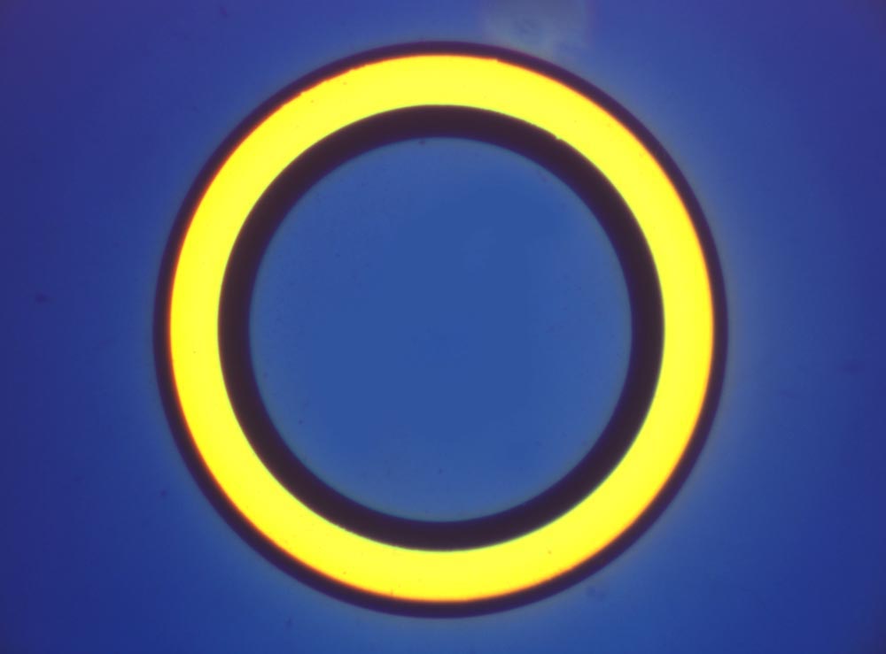 |
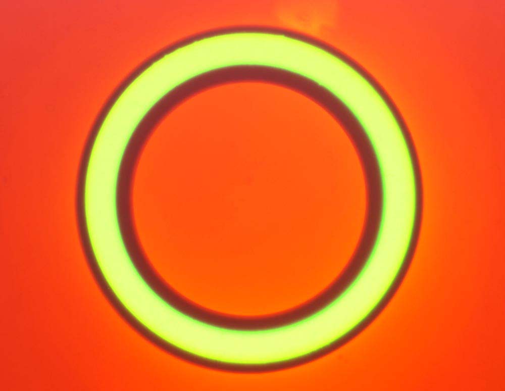
| Fig. 6. Appearance of the back focal plane of the 40/0.75 Ph2 Neofluar with Cokin red-green (left) and blue-yellow filters set up for colour phase contrast with Fluorescence-phase condenser. |
(The possibility of such a technique was clearly foreseen by Barer (1950) as "variable colour amplitude phase microscopy". He even saw the possibility of constructing "dichroic" filters whose spectral transmission would vary with the plane of polarization of the light passing through it. The method he proposed required the siting of a ‘zonal polarizer’, in the BFP of the objective, its plane of polarization at right angles to that of the filter/polarizer combination.)
Attempts to reproduce the effect by using a bright-field condenser in combination with two-colour illuminating discs produced photographically (on Fujichrome ‘Velvia’) were unsuccessful, though it was initially assumed that this might be the consequence of slight inaccuracies in the diameter and width of their annuli. That this was not the case was shown when Sergei Komarov used a computer graphics program to make extremely accurate discs as ink-jet and laser prints on acetate sheet, in a wide a range of hue and density combinations. These also failed to introduce contrast of any kind: all that happened was that the light rays passing through the narrow illuminating annulus appeared to be completely swamped by those transmitted by the much larger area of rest of the disc. At that time, I was unaware of the work done by Grigg, using illuminating annuli cut from gelatine filters, a technique most effectively demonstrated by van Wezel at the 2004 Reading Microscope Convention and reported in the Micscape magazine*. It then became obvious that failure with both the photographically-produced and the printed discs was merely due to the spectroscopic ‘impurity’ of their inks. This allowed considerable overlap between the wave bands diffracted by the specimen into the part of the aperture of the objective outside the ‘phase ring’ and those transmitted directly by the area surrounding the illuminating annulus. As a consequence, there were not enough of the rays of the apparent ‘colour’ of the illuminating annulus left to produce a significant image.
If the maximum diameter of the transmitted light illuminating beam is large enough, it may prove relatively easy to produce very satisfactory phase contrast images in shades of a single colour by using a simple low power condenser in combination with a coloured patch stop*. However, through the generosity of my friends at Applied Minds Inc., of Los Angeles. I was recently able to get discs of 32 and 16mm diameter cut with great accuracy from Cokin bicolour polarizers, using an abrasive waterjet machine. The 32mm ones fit the filter carriers of Zeiss (West) microscopes and thus facilitate applications in which the 60mm originals are inconvenient, to say the least. However, it is the availability of 16mm discs that is important here, since they may be used to replace the simple coloured patch stops mentioned above.
As described elsewhere, my experiments have been confined to the use of a Zeiss Ultraphot, fitted with a Neofluar 40/0.75 Ph2 objective and a Zeiss flip-top Abbe condenser with the iris diaphragm and upper lens removed. So far, the bicolour polarizing disks have been used to secure colour phase contrast in two ways:
A 32mm diameter disc with a concentric 24mm aperture was prepared from orange polyester film, using a Boehm wad cutter*, and this placed in the filter recess in the base of the microscope. A 32mm diameter linear polarizing filter was fitted on top of this, and a 16mm disc of red-green Cokin filter roughly centred on the upper surface of the substage condenser. The objective was focused on a suitable test object (mine is a mount of Navicula lyra in balsam). Then, with the Bertrand lens in position, the patch stop was accurately centred with respect to the phase contrast annulus (finger-tip control!) and the condenser refocused so that the image of the outer margin of the stop just met that of the inner margin of the annulus. (NB The field diaphragm needs to be is wide open and the condenser re-centred if necessary). The object should appear in some sort of colour contrast, however weak, and this is optimised by rotating the linear polarizer and tweaking the condenser focus to produce a vivid orange phase image against a green background. A rotating analyser may be used to increase the contrast. Note that this particular technique can yield extremely vivid colour contrast with anisotropic materials (fig 7.)
 |
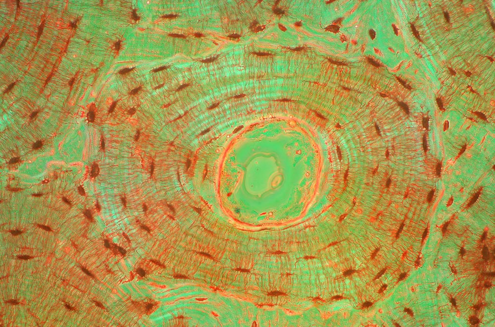 |
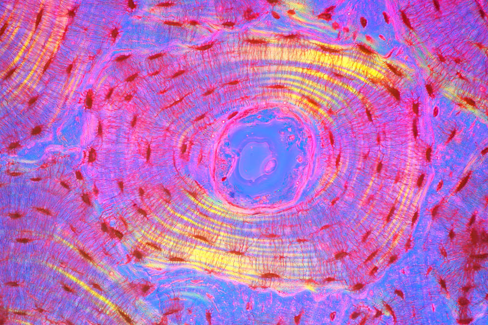
| Fig. 7. TS Haversian system, ground bone section, 25/0.65 Ph2 planapo, blue-yellow and red-green phase contrast images using bottom lens of Abbe condenser. HFW = 500µm |
As above, but with the linear polarizer and orange annulus replaced by a 32mm disc of red-green polarizer. The effect of turning this filter is less than inspiring, but the addition of the rotating analyser makes it possible to obtain both red-on-green and green-on-red phase images with excellent contrast. With discs of blue-yellow filter the images are yellow-on-blue, blue-on-yellow, and so on.
BIBLIOGRAPHY
Barer, R., 1949, Variable colour phase contrast microscopy. Nature 164: pp.1087-8
Bennett et al, 1951, Phase Microscopy. Wiley & Sons.
Grigg, F.C., 1950, Colour-Contrast Phase Microscopy, Nature, Vol., 165, no.4192
Kirkpatrick, D., Nov. 1998, 'Bicolour Polarisers'. Photon Magazine Vol. 6, no. 10 pp.36-7.
Ray, S.F., 2002, Applied Photographic Optics, 3rd Ed., Focal Press. ISBN 0 240 51540 4
Rothschild, N., 1976, 'Dial Your Colour' Popular Photography. 40.
van Wezel, R, March 2004, MicScape Magazine ‘Colour Phase Contrast’
Walker, M. I., 2006,. ‘Colour phase contrast with a simple condenser’
|